The supercritical airfoil shown in figure three is the SC(2)-0412. These two features cause for the supersonic flow to occur closer to the surface as well as maintain low local supersonic Mach numbers, and finally the terminating shock wave occurring over the and below the airfoil are much weaker than other airfoil families. The most obvious feature of this airfoil is the tail and the flat top. Figure 3 illustrates the shape of a supercritical airfoil. The goal was to increase the drag-divergence Mach number and allow for more efficient flight in the transonic regime. This section describes a completely different family of airfoils that were developed during the 1960’s and 1970’s by NASA strictly for the purpose to reduce the onset of drag due to the formation of standing shocks from local supersonic flows over the airfoil. This airfoil was also the stepping stone to the supercritical airfoil. This family of airfoils became widely popular due to the ability to increase the critical Mach number compared to other NACA airfoils at the time. The third number represents the design lift coefficient tenths, and the last two digits give the maximum thickness in hundredths of a chord.
#Chord line of an airfoil series
In this family the first digit implies the series the second digit specifies the location of minimum pressure in tenths of chord from the leading edge. This family of airfoils was developed during World War II they are laminar flow airfoils which have no sections of turbulent airflow. The alternate way of describing this airfoil is through percent of chord, for example: 4 percent camber, 40 percent chord with 15 percent thickness. Thus for the NACA 4425 the maximum camber is 0.04*c located at 0.4*c from the leading edge, and has a maximum thickness of 0.15*c. The last two digits (15) give the maximum thickness in hundredths of a chord. Using the NACA 4415 shown above in figure 2 as an example, the first digit (4), represents the maximum camber in hundredths of chord, the second digit (4) is the location where the maximum camber is located along the chord from the leading edge in tenths of a chord. The NACA “four-digit” airfoils were the first developed in the early 1930’s. NACA developed a large database and produced several naming conventions for different classifications using a numbering system. Airfoil shape design was a much customized art early on, however in 1930’s the National Advisory Committee for Aeronautics (NACA) performed an exhaustive amount of design and testing of various airfoil shapes. The Wright brothers experimented and tested their own shape designs as well. Phillips patented his first airfoil shapes. These cross-sections come in all variants of thickness, camber, and chord length. Changing the angle of attack also influence the behavior of an airfoil.


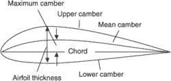
The camber of the airfoil is the dominant characteristic which influences the lift, drag, and moment produced by the airfoil. The camber is then said to be zero since it is the maximum distance between the chord line and the mean camber line.


When the mean camber line and the chord line lie directly on top of each other the airfoil is symmetric. The distance then between the leading edge and trailing edge is simply the chord and it is denoted by the letter c. The chord line is a straight line drawn from the leading and trailing edges of the airfoil. The mean camber line is equidistant from the upper and lower cross section, essentially a dividing line where the thickness is equal above and below. Further investigating this cross-section, Figure 2, illustrates several design features.The most important design feature is the mean camber line, shown in figure as a dashed line spanning the length of the chord. When the vertical tail induces a rudder deflection the local flow is turned and results in a yawing motion.Īn airfoil is best visualized as the cross-section of a wing as shown in Figure 1. All control surfaces are in essence are airfoils. In aerospace applications airfoils are not only utilized on the wing. Other sources define airfoils to be any shape or surface designed to turn flow. NASA defines an airfoil to be a “streamlined surface designed in such a way that produces useful motion.” The useful motion being referred to in aerospace applications is lift or propulsion depending on where the airfoil is utilized.


 0 kommentar(er)
